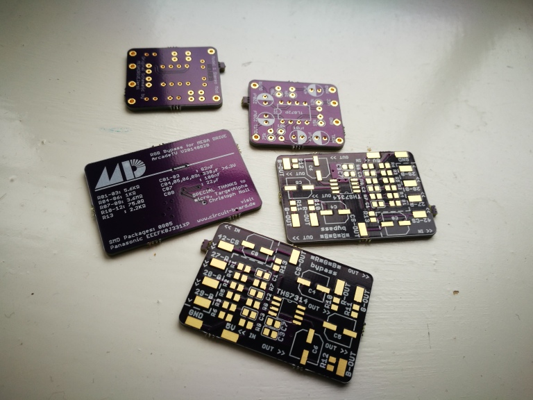
For a while I’ve been interested in purchasing an RGB bypass board for the Mega Drive. The circuit, designed by ArcadeTV (and detailed here) uses the THS7314 RGB amp, popular in SNES and N64 RGB mods, to obtain a far superior image than the stock amp with none of the infamous “jailbars” that the MD suffers from. Unfortunately, I’ve been unable to find any of these boards online to purchase.

A couple of weeks ago I came across a nifty site called oshpark, a community based PCB sharing and printing service – and found the RGB bypass board on there! Prices were cheap, a few dollars with free shipping to the UK, and I have lots of soldering/modding experience…so why not? I put an order in for the Mega Drive RGB bypass board, Borti’s SNES SPDIF/Optical audio out board, an optical audio out board for the Saturn and an amp circuit for direct line output from the Mega Drive for vastly improved audio than the front jack. 3 boards minimum per order so I had spares if I messed up and the possibility of some to sell after. I then ordered all the components needed (resistors, capacitors, bypass chips, cirrus digital audio chips etc, from aliexpress. Everything turned up within a couple of weeks.
I realised afterwards that I had accidentally ordered the first revision of the Mega Drive bypass board and not the second…so I ordered some of the second. I’m impatient so I just decided to press on with the v1 board and swap it over when the second arrives
Anyhow! I got to work.
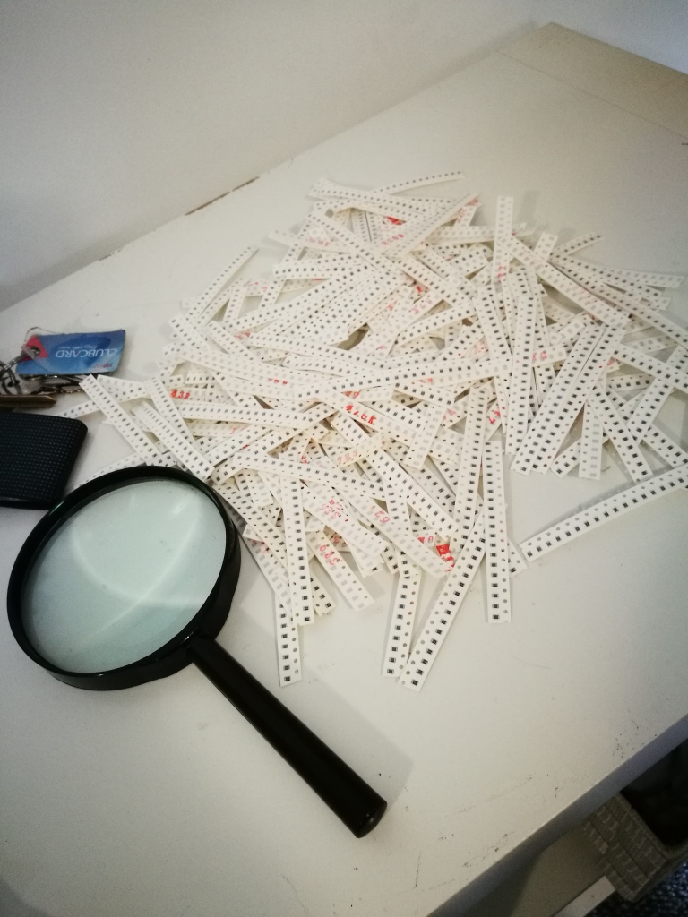
The type of SMD components needed were of 0805 pitch. I only needed a few, but it was cheaper to buy in bulk. Unfortunately they turned up with no markings – so I had to go through all 40 sets!

Once I pulled out the ones I needed (and labelled them), I put the board together. Was relatively simple, just needed a steady hand and decent application of flux!

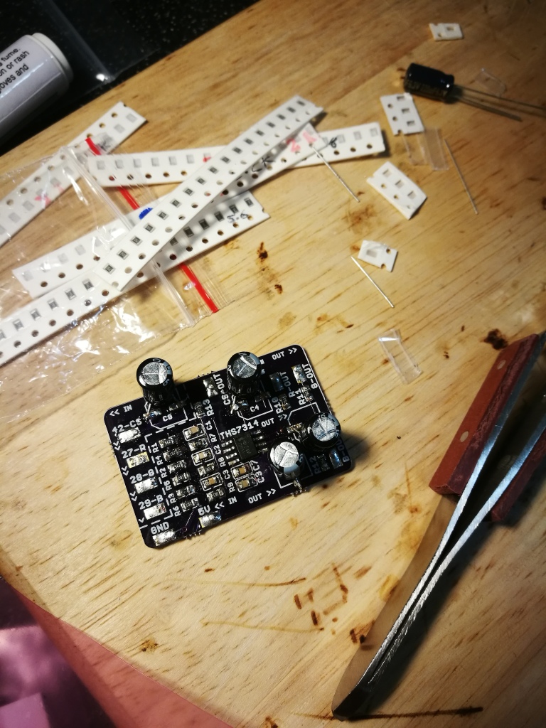

The board specified use of SMD electrolytic capacitors…but I didn’t have any, so I used standard ones of the same spec. They do the same job, they just are a bit more fragile. Not an issue, as I won’t be messing with it or posting it out. Now to install it! Firstly, I removed the RF module. No one should be subjected to RF, so I did the world a favour by chucking it in the bin. It also gives me a nice place to put the RGB board (secured via strong tape) and somewhere to mount my new audio jack when I install the direct amp.
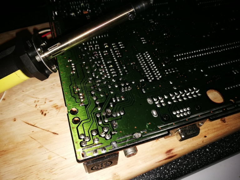


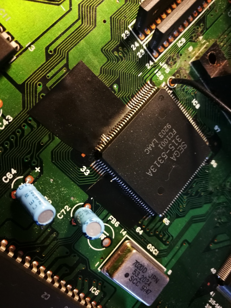
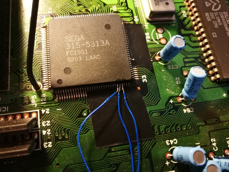
I then found the main PPU and carefully lifed the R,G,B and sync pins using a scalpel before isolating them with tape and soldering the wires up.
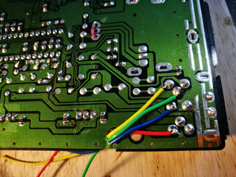
As I won’t be using the stock RGB amp any longer, and I wish to use the stock multi-out, I have to cut the RGBS lines from it. So I got my cutters and chopped away:

Now…to hook the amp up! Easiest part.


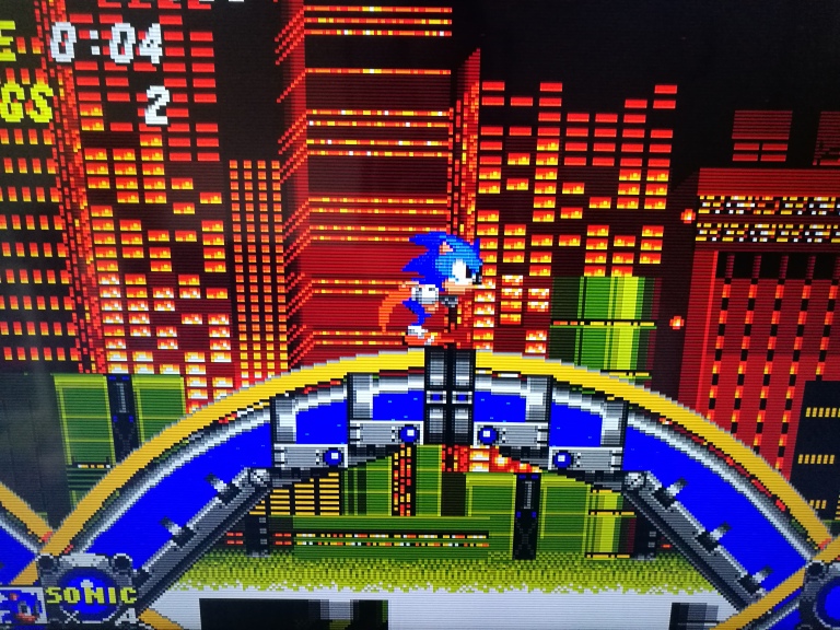
Now…to test it! Hooked it up to my OSSC and hoped for the best…

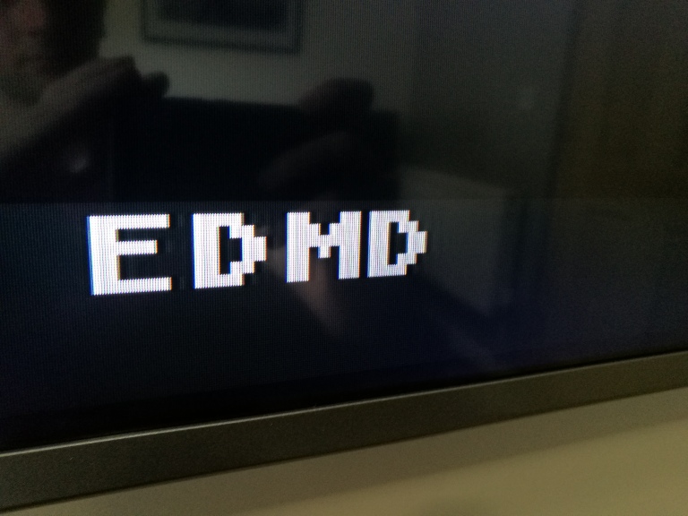


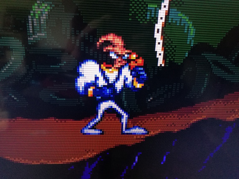
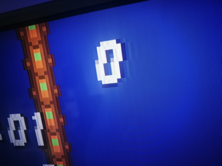
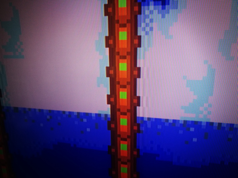
Very happy! The difference is immediately noticeable – a pixel-perfect image with no ghosting, jailbars or double images! I have noticed the brightness has taken a slight hit, so I need to lower or remove the resistors in the SCART cable – but that’s easy. good times.
Some more images: